Last Updated on Mar 18, 2022
Are you interested in welding? Have you wondered what is MIG welding? Considered to be one of the easier types of welding to learn, MIG welding is used for welding various types of metals, including stainless steel, carbon steel, aluminum, copper, nickel, and other alloy metals.
In the past decade, MIG welding has gained another name, Gas Metal Arc Welding or GMAW; however, everyone still refers to it as MIG welding. Below we have created a guide, MIG welding for beginners, that we will explain the basics of MIG welding
MIG Welding Process
MIG welding stands for Metal Inert Gas and uses an arc of electricity to create a short circuit between welding wire and metal. The short circuit produces heat that, when mixed with inert gas, welds the materials together.
Benefits of MIG Welding
Although it can only join metals of thin to medium thickness, it can join a wide range of metals and offers a good bead. It also provides the capability for all-position welding, minimum weld splatter and is easy to learn.
How to Set Up for MIG Welding
To set up for MIG welding, you will need a welder, wire, gas supply, welding torch, movements, techniques, and metal thickness. Below we will go into each item needed for MIG welding to explain MIG welding basics. You should also make sure you have the proper safety gear to reduce your risk including welding jackets.
Welder
The welder is what holds the spool of wire for welding. Inside you will find rollers that push the wire towards the welding torch. If your wire should jam up, you will need to open the case and review the feed assembly to fix it. On larger MIG units, the wire feed unit may be separate. Compact MIG welders generally have an internal feed assembly.
MIG Wire
MIG welding wire is a filler metal that is the same type of metal that is being welded. For example, if you are going to weld stainless steel, you will need a wire made of stainless steel.
The most common wire types are carbon steel, stainless steel, and aluminum. In addition, most wires now include elements like manganese or titanium to help with deoxidizing the weld and create a strong arc. Steel electrode wires come coated with some copper to avoid oxidation. As a result, the percentage of these elements may differ from wire to wire.
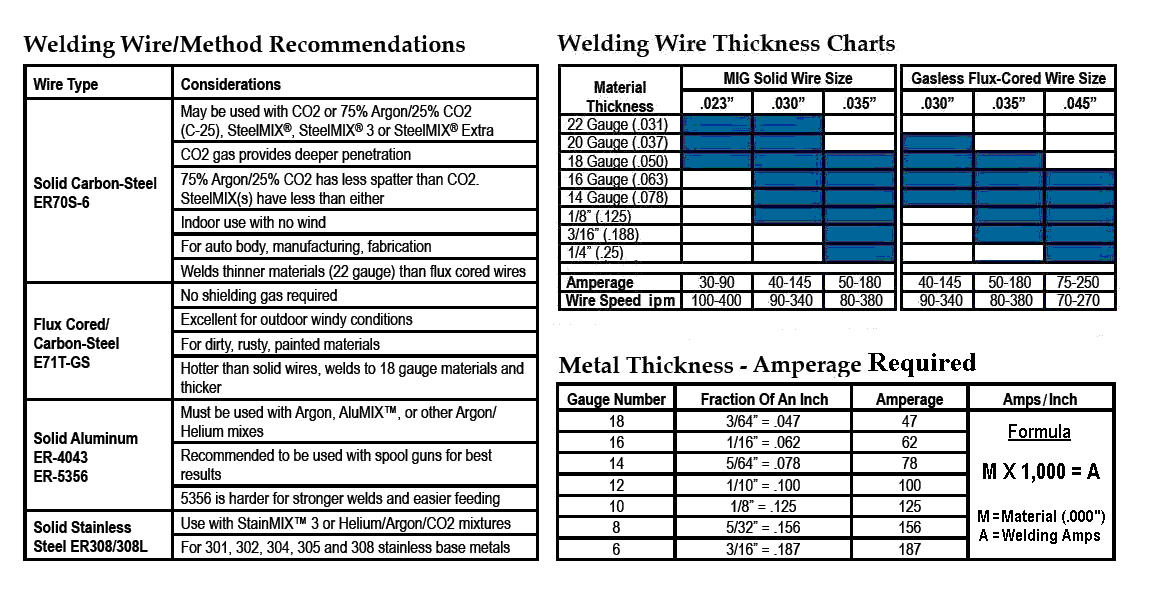
MIG Wire Sizes
Typical wire sizes range between a thickness of 0.023 to 0.045 for welding light to medium duty applications. For heavy-duty applications, a thicker gauge wire will be needed.
Installing Mig Wire
When installing the wire, you will need to first prep the wire reel tensioner by tightening it, so the wire doesn’t unravel under its own spring tension. Next, the first three inches will need to be straight as possible before feeding the wire through the guide tube towards the roller.
At this point, the small hole of the wire liner at the end of the MIG welding gun needs to be visible. Here the wire needs to be pushed through and should feed easily without force. If force is required, then most likely, the wire has missed the liner. Often it is suggested to remove the contact tip at the end of the torch before feeding the wire through. When installing, it can be helpful to use a welding table for stability of your project.
With the wire pushed into the liner a couple of inches, replace the tensioner and turn on the mig welding settings for the wire feed mechanism to push the wire through the liner. Remember to keep it as straight as possible as you reach the torch end. Finally, set and check the tensioner on the roller and the wire reel.
Welding Gas
For your MIG welding gas, it will either be 100% Argon or a mixture of Argon and CO2. This gas will shield the weld as it forms. Without gas, the welds will look brown, splattered, and not aesthetically pleasing. You will want to open the main valve of the gas cylinder to make sure that there gas inside.
The MIG welding gas pressure gauge should read between 0 and 2500 psi, and the regulator should be set between 15 and 25 psi. These are general settings and will be dependent on the welding torch performance and how you like the weld.

Porosity
Porosity in welding is the presence of cavities in the weld. This can be caused by several things such as leaks in the gas line, draughts and excessive turbulence in the MIG welding beads pool, or too high a gas flow rate.
To avoid porosity, check the flow rate and leaks, keep a good contact tip to work distance, avoid drafts, ensure the surface welded is clean, and watch the travel angle. There are several types of porosity in welding, and they are distributed, wormhole, surface-breaking pores, and crater pipes.
Gas Types
There are four main types of gas for MIG welding: Argon, Helium, Carbon Dioxide, and Oxygen. The primary task of shielding gas is to protect the weld pool from the atmosphere, prevent nitrogen and oxidation absorption, and stabilize the arc.
The basic MIG welding gas is Argon. Helium can be added to increase fluidity and penetration to the weld pool. Argon alone and Argon with Helium can be used for welding all grades. Also, O2 or CO2 is added to help stabilize the arc and improve both fluidity and the weld deposit’s quality. To note, for stainless steel, gasses will contain small quantities of Hydrogen.
Gas Safety
When handling and using gas cylinders for welding, the following safety precautions should be taken.
- When storing or moving cylinders, cylinder valves should be closed with caps on and placed in dry space vertically. Avoid dropping cylinders when moving them.
- Remove the regulators if possible. If not, ensure the cart has at least a 10 lb. ABC rated fire extinguisher. Note: Regulators are to be removed after use unless the setup will be used within 24 hours.
- When hoisting and moving cylinders, use a pallet, sling board, or cradle. Never use a magnet or choker sling.
- While welding, protect the cylinders from flame, hot slag, or sparks. Either create space if possible, use shields or cover them with fire retardant blankets.
- When lighting torches, use friction lighters.
- If the cylinder is empty or work has been completed, ensure valves are closed, and the caps are on.
- Regulators, hoses, etc., should be stored in a dry area like cylinders. In addition to dryness, the area should also be well-ventilated.
- Oxygen cylinders should have a firewall or at least a minimum of 20 feet when being stored.
- All hoses and lines at the manifolds and gauges must use flashback safety valves.
Nozzle & Electrode Stickout
With your torch, you have a variety of welding nozzles to choose from. The main purpose of the nozzle is to direct the gas into the weld puddle as efficiently and as effectively as possible. Therefore, welding nozzle choice will be determined mostly by the process, application, and access to the joint.
There are welding nozzles that allow for better gas coverage, whereas other nozzles offer better access. Welding nozzles for a MIG torch will either be made of copper or brass; some are nickel-plated. Torches will only accommodate threaded or slip-on nozzles. The various types of welding nozzles are:
- Conical
- Bottleform
- Cylindrical
The nozzle you use will determine your mig welding tips placement. There are also flush, stick-out, and recessed welding nozzles. Flush nozzles, MIG welding, will be done in short circuit mode. This type of nozzle can be prone to spatter because the tip will sit in line with the nozzle’s bore.
As the name implies, a stick-out nozzle allows the contact tip to “stick out” from the nozzle. Stick-out nozzles are generally used for welding with tight access. However, for spray or pulse mode MIG welding, a recessed nozzle will be used. Recessed contact tips with a longer wire stick-out are used with this nozzle. This nozzle will allow the gas to encase the contact tip at higher amperage and then flow to the weld piece.
Polarity
To correctly MIG weld, your polarity settings need to be adjusted for the wire you use. For example, if you are using flux core wire (gasless) and have the welder set to the wrong polarity, you will notice a lot of spatter.
To understand the difference, let’s review the purpose of the shielding gas. Gas is used to shield the weld pool from contaminants. There is already a shielding agent in the wire with flux core wire, so when the arc occurs, your shielding agent is present.
For gasless or flux core wire, your polarity needs to be set to direct the current electrode negative (DCEN). With DCEN, the electrons flow from negative to positive. Thus, the electrons move from the machine to the torch, then through the workpiece and ground cable, then back to the machine.
As for DCEP, Direct Current Electrode Positive, the electrons travel in reverse.
When setting polarity, the manufacturer’s specifications will determine the polarity. Most electrodes (7018, 8018, etc.) are positive. Likewise, wire-fed welding wires that will require gas shielding (solid wire, flux core with gas, etc.) are positive.
Self-shielded wires (flux core gasless) are electrode negative. However, there are some self-shielded fast-fill wires electrode positive. Ultimately, polarity depends on the manufacturing process and will be noted on the specification sheet.
Voltage
Four main variables affect the penetration profile and the weld bead profile: current, voltage, CTWD, and travel speed. For MIG welding, it commonly uses a constant voltage power source. This allows for a relatively consistent output over a range of welding currents.
Welding voltage controls the arc length between the weld pool and the wire. As voltage is increased, the weld bead flattens and has an increased width to depth ratio. For a CV MIG welder, it will select the wire feed speed (WFS) on the wire feeder unit and select the correct voltage on the power supply. From there, the current is supplied. Wire feed speed and current are interrelated, so changing one affects the other.
Wire Feed Speed
Wire-speed is probably the most important setting on a MIG welder. Unfortunately, when it comes to wire feed setup issues, it is generally caused by speed adjustment problems. Something that helps with adjusting wire speed is to test it out on a scrap piece of steel.
Set the welder to the correct power setting for the metal’s thickness, and then weld. While welding, alter the speed until you get close to what you need. Below we have listed common issues that occur at certain speed settings.
Too slow: The wire makes occasional contact with metal. When contact is made, the wire forms a ball and then melts back to the contact tip (burns back).
Slow: Wire still burns back at contact, but process is quicker.
Good: Wire is moving fast enough to provide constant arc to the metal. The sound of the weld is consistent.
Fast: The weld is consistent but sound and penetration is increased. Crackling or rapid-fire sound occurs.
Too fast: The wire is moving fast and bends on contact with the metal. The torch feels as though it’s being pushed back. At this speed, there will be a lot of spatter.
As noted above, wire-speed controls the welding current. Therefore, increasing the wire speed beyond a nice consistent weld will ultimately increase the current, resulting in blow-through on thinner steel.
Mig Welding Modes
There are four modes to MIG welding: short circuit, globular, spray, and pulsed. Each one is explained below.
Short Circuit - Also known as dip mode, is continuously fed solid or metal core wire during repeated short circuits. It has an all-position capability and is a low heat input method.
Globular - This mode is also continuously fed solid or metal core wire. It deposits short circuits and gravity-assisted large drops. This mode does not require the wire to be in contact with the metal and is capable of high-speed welds.
Spray - With continuously fed metalcore or solid wire, this mode is high energy. It deposits small droplets that make a visually pleasing bead with a high disposition rate.
Pulsed - This mode is a highly controlled variant of the spray mode. This mode has the greatest number of advantages compared to the other modes as it offers high resistance, no spatter, welding out of position ability, lower levels of heat-induced distortion, and 98% electrode efficiency.
MIG Welding Technique
With your welder setup, you are ready to get started with learning how to weld. There are several variables concerning welding and they are:
- Torch Movements
- Types of Beads
- Welding Positions
- Welding Joints
- Thickness of Metal
Torch Movements
When welding, you cannot just push a straight line across a joint. There are two particular movements with welding; forehand, also called pushing, and backhand, which is pulling. Whenever possible, most will use the push movement, but often you may find yourself using both.
Forehand / Pushing - Pushing is the most common welding movement. The torch needs to be held at a 10-degree angle with the electrode facing the direction you will be welding. With position set, pull the trigger and push forward, making sure the electrode is pointing towards the leading edge. This position allows you to see the weld joint.
Backhand / Pulling - As with the pushing position, hold the torch at a 10-degree angle and pull towards your body. This position allows for more penetration; however, it does increase the chance of contamination to the weld.
Types of Beads
Several types of beads can be laid when welding. Below we have listed them in detail to understand how to create them.
Stringer Bead: This is the most common bead type. This requires the push position across the joint in a straight line. These are generally thinner welds.
Cursive “e”: The cursive e bead links the weld bead and is a good choice for thicker metals. This bead gives a clean scaled effect.
Cursive “v”: By going zigzag, this bead overlaps like the cursive e, leaving behind a better weld deposit. This bead is often used for overhead welds to prevent dripping.
Welding Positions
There are several welding positions that suit specific applications. There are a total of four positions that help to create the MIG welding patterns mentioned above, and they include:
- Flat
- Horizontal
- Vertical
- Overhead
Flat Position
The flat position is one of the most common, where the metal being welded will lay flat. The bead will be laid above the joint and horizontally.
Horizontal
The horizontal position is used for groove and fillet welds. When in this position, you have to watch for the bead to sag. To combat gravity, hold the torch at 45-degrees from the joint and point the electrode 10-degrees. This is where a forehand cursive e bead will be utilized.
Vertical
The vertical position is used in structural welding when the weld’s axis is vertical or more than a 45-degree incline. This position requires more skill than the first two positions. Often this position is called vertical “up” or vertical “down.”
The electrode is typically pointing up when in the vertical down position. For the vertical up position, hold the torch at the same angle but pushing up the joint.
Overhead
This position is one of the hardest to perform. The cursive e or v will be the best bead to lay for this position to keep dripping minimal. The nozzle should be kept close to the piece you are working on.
In this position, it is paramount that your head and body are properly covered. It’s suggested you keep the arc low and move fast.
Types of Welding Joint
When creating a joint to weld, you will find that there are a few to choose from. Below we have listed the four most common joints.
Butt Joint: This joint is created when two pieces of metal are put together edge to edge. This creates a seam for you to lay your bead.
Lap Joint: To create this joint, the two pieces being welded will overlap one another. You can perform a single or double lap joint. A double lap joint is the best when welding something for a structure under load. This joint is also called a fillet joint.
T Joint: A T joint is used when a weld requires a 90-degree angle. The two-piece comes together to form a T with beads laid on both sides of the vertical piece.
Corner Joints: For corner joints, the two pieces will form the letter L. These are tricky joints when the metal thickness is less than 1/8″.
Metal Thickness
Metal thickness comes into play when trying to create a good, strong weld. There are three thickness levels: low, medium, and high. Each requires bevelling with a grinder to obtain a strong weld except for low thickness metals. With 1/8″ or less it’s best to keep the electrode close to the joint. On thinner metal, watch your distance, so it does not burn through.
Medium thickness metals will require bevelling on one of the pieces. This allows the bead to lay directly down between the two pieces. Beveling both sides of the metal will be needed on high thickness metals. This is typical in professional industrial welding and is not generally necessary for hobby welders with a 140A welder.
To assist with wire and metal thickness, you can refer to this MIG welding chart.
Have you seen these other guides?